Web 2.3k 249k views 4 years ago hvac wiring diagrams & schematics i show the low voltage thermostat wiring diagrams for heat pumps, electric strip heating, furnaces, air conditioners,. Web i show the low voltage thermostat wiring diagram for a heat pump with electric resistance strip heating in the air handler. Web here is the industry standard color code for thermostat wires used for most systems:
Wiring Diagram Hvac Thermostat Module Wiring Diagram
Web first is the basic wiring diagram.
Top Of Page Free Shipping In The Usa!
With the top thermostat wiring diagram showing an air conditioning system. I explain what each of the letter. Web basic auto air conditioning wiring diagram how to ac compressor clutch relay parts:
Then Different Wiring Setups Are Discussed Such As Using Emergency And/Or Auxiliary Heating And 2 Stage Heating And Air Conditioning.
In this hvac installation training video, i show how to wire the low voltage thermostat wires into a furnace and ac unit. Turn the electricity back on to the furnace and air conditioner. The y wire is yellow and connects to your air conditioning compressor.
Use Wire Connectors To Secure All Connections.
Web 1st stage heat (white) 24 volt+ fan only operation common air conditioning standard thermostat some ac systems will have a blue wire with a pink stripe in place of the yellow or y wire. If your thermostat controls your heat, you will have a white wire. Tape all exposed wires to prevent accidental contact.
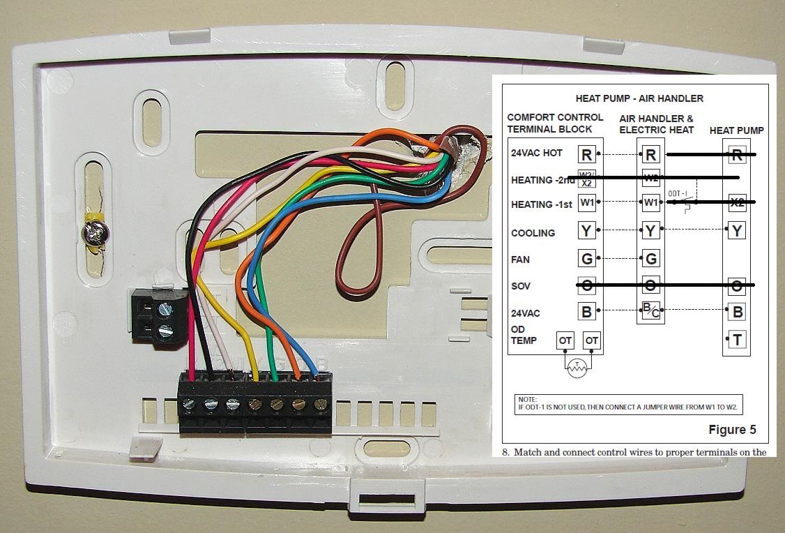
The Second Wiring Diagram Showing A Heat Pump System.
At every stage, we will point out what 2 wire or 5 wire thermostats are used to wire, for example, to get a bigger picture of where those color wires go and how they enable the functions of air conditioners and furnaces. Use the correct gauge wire for the power source. These two connections will ensure that there is power to the thermostat that you are operating.
Batter, Ac Selector Switch,Blower Motor, Aux Fan Motor, Compressor Catch Coil, Resistor Block, Fuse, Compressor.
Web basic thermostat wiring for furnace and air conditioner. Web furnace wiring diagram. Finally, the third thermostat diagram showing the average type of split system with an air conditioner or gas or oil furnace used for heating.
The Diagrams Include The Wire Colors, Component Locations, And.
You might not need all the wires. The o wire reverses the valve from heating to cooling, and the b wire switches the valve from cooling to heating. Web tips for wiring a ac thermostat always follow the wiring diagram carefully.
In This Article, I Am Going To Explain The Function And Wiring Of The Most Common Home Climate Control Thermostats.
Web you can wire a thermostat to your ac in 5 quick steps that involve labeling the wires and connecting them to the control board. Flip the switches in your breaker box to restore the electricity to the items. Just like the y wire, the w wire (s) control the heating aspect of your system.
I Show Where The Wires Go At The Thermostat, The Color Code, Then Down At The Furnace Control Board, And How To Wire Up The Wires Coming.
Web as shown in the diagram, you will need to power up the thermostat and the 24v ac power is connected to the r and c terminals. Web a tempstar ac wiring diagram is an electrical schematic that shows how the components of a tempstar air conditioning system are connected. This gas furnace wiring diagram is a guide to wiring most thermostats that will control a gas furnace system whether or not it includes an ac unit.
Web I Discuss How To Wire The Contactor And.
These wires are responsible for switching the changeover valve in a heat pump system. That control can be digital or analog, but it all ends up going through the thermostat wires. Test the thermostat by causing the furnace and air conditioner to come on at various temperatures.
Various System Configurations And Thermostat Wiring Including 4 Wire, 5 Wire And 7 Wire Thermostats Are Discussed On This Page.
Web ac thermostat wiring (diagram explained for hvac) written by josh mitchell last updated on may 21, 2023 hvac systems need control points and those come in the form of thermostats. Web see the diagram below for the role of each wire in your system: The g wire is green and connects to the fan.
The W Wire Is Connected To Your Heating System.
Web it should sit flush against the wall and be straight. Web a look at thermostats and climate control within the home for heating, air conditioning, fan auto/on, terminal labels, wires needed and more. The color of wire r is usually red and c is black.
Web Check Out Multiple Thermostat Wiring Diagrams As Well As In Depth Video Explanations On Accurately Wiring Thermostats For Various Types Of Hvac Systems!
I discuss the color code and volt. The heat pump wiring diagram shows the wiring colors to attach to each terminal. This is the most common wiring setup for a.
C Is Known As The Common Terminal.